Making the world’s smallest game console
How small can we make a console that’s still playable?
Before we begin, let's quantify what qualifies as a video game console. Since we are talking about video games, some kind video output is non-negotiable. An interactive medium definitely needs some kind of human input. Sound is theoretically optional, but even the most basic audio is better than none.
Since we are going for small, usability is a concern. For a portable console, I think a watch gameboy is about at the limit of playability. At the extreme, we also have Thumby, a portable literally smaller than a thumb. Instead, we will go for a "home" console — of the type that connects to your television. For input, we have a lot of choices. I decided to go with a regular Xbox gamepad and I will assume that we won't take it's size into account, as that's not what one typically means about when talking about size of a console.
Given these constraints, we can go as small as we want. Once you are done reading this post, you might have ideas on how you could make something even tinier — in fact my intention is to include a little bit of a challenge in my title choice for this post.
To make this challenge more fun, I will throw in one extra constraint: we should be able to play Doom. Because of course we should.
Choices
The console will be based on everyone's favourite ESP32-S3. The chip has plenty of compute, is cheap, small enough, can run off battery and there are lots of resources available. The built-in radio will come in handy for interfacing with human input devices and WiFi is a bonus. We will miss some useful peripherals like a generic PLL, DMA-capable parallel port or a fast DAC, but we will hack around those limitations.
For video output, we have a couple of choices. Graham Sanderson made Doom run on RP2040 with VGA output. It's certainly possible to do DVI/HDMI with the RP2040 as well.
It would be nice if our home console was compatible with the same TV sets the consoles of the past supported. In order to achieve this, we need to output an analog TV signal — in the case of my region, PAL. And honestly, learning this obsolete art was part of the motivation for this project.
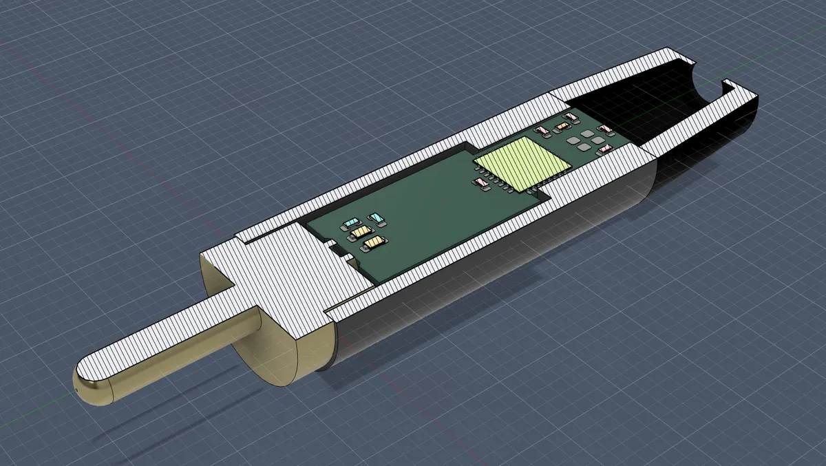 Earlier attempt at fitting the circuit in an RCA plug
My original idea was to make the entire thing fit in an RCA plug and generate composite video. That would definitely push it to the extremes of smallness. There are two problems with that however. One, since the connection doesn't carry power, we'd need a battery.
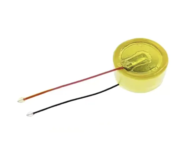
There exist Lithium-Ion batteries that would fit in the dimensions, like the 8.5mm diameter one pictured here. They are often used for in-ear wireless headphones. Unfortunately, those tend to have very little capacity, and more significantly, can't deliver enough current to power the ESP32-S3 system (which ended up consuming about 120mA with BLE enabled).
Two, we can't play sound through the composite video connection. We would either need separate connectors or a different way to get audio out — perhaps a tiny built-in speaker or Bluetooth LE audio. Those options kind of suck though — very few devices support BLE audio (most wireless headphones use a classic Bluetooth audio protocol) and we can't expect sound quality of any kind from such a tiny speaker.
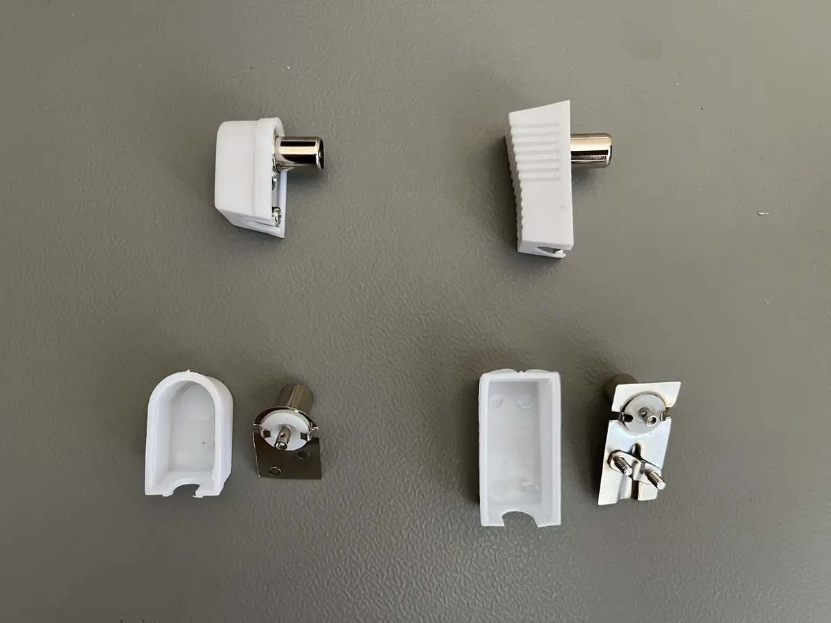 9.5mm antenna plugs
Instead, I chose the even more old-school route. We are going to give ourselves a built-in RF modulator and connect straight into the antenna receptacle. The multiple variants of the PAL standard define how to put sound on top of our signal, typically through FM. There are a couple of 9.5mm antenna plugs that are just the right size to fit a PCB and a battery inside — the ones pictured are a couple of Goobay-branded I managed to find.
For input, I went with the Xbox series X controller, as it's quite common and conveniently talks over BLE.
Analog TV — getting an image on screen
Dedicated analog TV output silicon is not something you are likely to find on any modern microcontroller. On the other hand, these day we have sufficient compute to synthesize an analog TV signal directly. An example of that and a major inspiration for this project were bitluni's and CNLohr's explorations on an ESP32. The newer variant of the chip, the ESP32-S3, doesn't come with a DAC fast enough to achieve it directly (there is a rather low-bandwidth 8-bit Delta-Sigma peripheral only). That doesn't mean we can't make our own though with a bunch of resistors. After all, what else is a parallel digital port than a DAC waiting to be born?
Now, I said there is no DMA-capable parallel port on the chip. While there isn't a generic one, we have the RGB LCD output peripheral we can coerce into doing what we want. This peripheral is designed for image output, but it's not quite in the format that we want. For PAL color, we need to mix in QAM-modulated Chroma signal on top of our Luma (brightness), meaning we need about 6MHz of bandwidth at least. We also need to take care of PAL's color bursts and phase-alternating. Fortunately, that is something we can synthesize in software, and the ESP's LCD thing will take our bytes with no complaints. To get the timings right, there is a bit of data transfer acrobatics necessary that I won't get into here. The Espressif documentation gives a decent elucidation of the pitfalls.
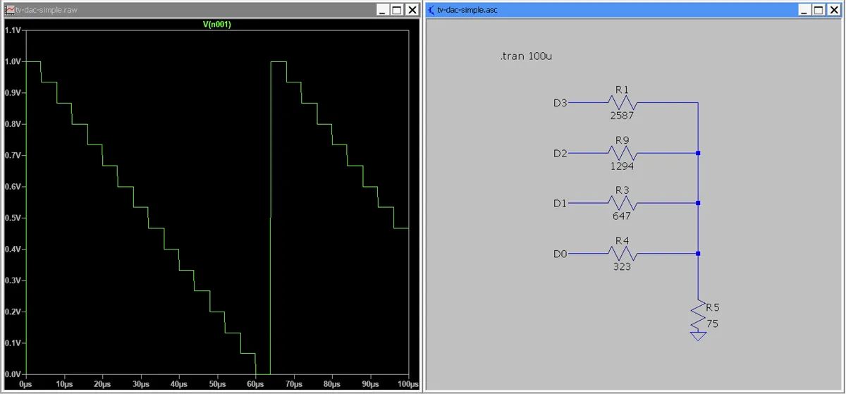
In an attempt to minimise the number of external components, I started with just a 4 resistor DAC. Unlike an R-2R ladder, the value of each resistor is different and chosen so that with a 75 ohm termination (standard in television) we should end up with a 1V range. To find the individual resistances we will use superposition:
When all data pins are high, output voltage should be our peak 1V:
When each of the individual data pins is active on it's own, we should get increasing powers of 2:
therefore, we have:
Use the voltage divider formula to find the resistances. Our output voltage is between on the 3.3V side and all the other resistances, including the load, in parallel on the 0V side:
Solving, we get:
We end up with an output impedance of . Quite far from our preferred 75 Ohms, but we don't worry that much, as we will be plugging directly into the the TV's input, not to a long coax. With composite video, we are dealing with wavelengths over 50m long. Reflections shouldn't be a huge concern.
Composite video from a 4-resistor DACThis topology was enough to result in a playable rendering of Doom, however the color resolution is quite poor with just 16 voltage levels. There was also visible color distortion, which perhaps could be attributed to loose resistor tolerance of the prototype.
I did not bother with measuring glitch (high energy spikes resulting from individual data lines not switching at the exact same moment) at this point, but with a resistor network DAC that is something to consider.
How the composite signal is synthesized
I'm not going to go into a whole lot of detail on what goes into a PAL composite signal in general, as that's been explained in detail in plenty of other places. In short, the image is scanned out line by line. We have a bit of synchronization signalling at the beginning of the line and we end with a blank front porch. In the middle, each line's lower frequency component contains the luminosity (brightness) signal, same as you would have in a black and white television system. Riding on top is a higher frequency subcarrier encoding the color. Specifically, the YUV color space is used, Y being the luma and the other two components get encoded into the phase and amplitude of the color subcarrier (the Chroma) — an analog flavour of the QAM.
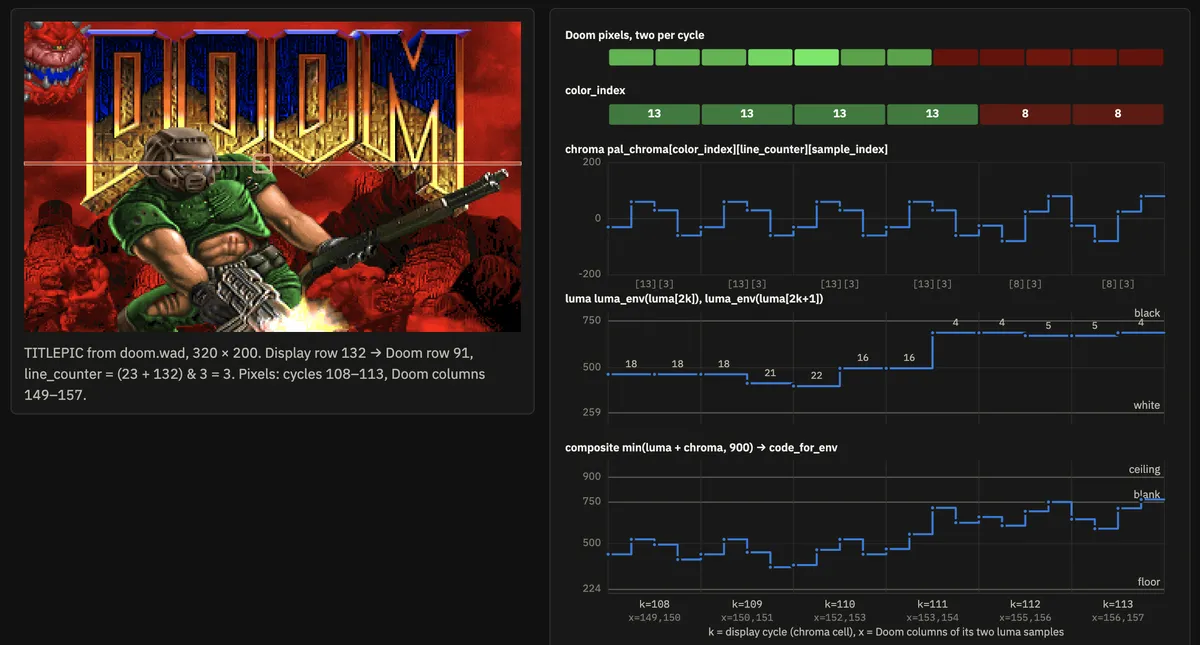 Stitching a signal together from waveform bits
The main trick we can use in our signal generator is to precompute single-cycle waveforms for the entire color palette, in each variant they can appear (we end up with 4 line-number-dependent variants as in PAL the chroma's phase is supposed to rotate line to line). In our case, we keep 4 samples per cycle per color. We also squeeze out a little bit more resolution by keeping two luma pixels per one chroma cycle/pixel.
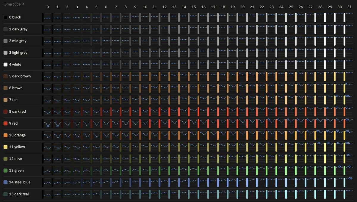 (color index, luma) waveform LUT, 1 of 4 line number variants
Before going out to the DAC, the sum of luma and chroma goes through a calibration curve to try and correct for the output section's nonlinearity. To avoid the time cost of a double memory lookup, the entire pixel rendering process happens as a lookup into a single 8KB long array indexed by (color index, line counter variant, luma value).
The line constructed in this fashion, including the timing and blank bits, is written to another buffer, which DMA takes care of scanning out in time. One slightly annoying part of abusing the LCD peripheral for this purpose is that it will insert it's own sync intervals, forcing the data pins to 0 for their duration — something to pay attention to when most of the signal is software-defined.
Radio crimes — path to sound
Now with composite video working, we can think about modulating it up to a broadcast channel frequency and putting sound on top.
To generate a carrier frequency we're going to take advantage of ESP32-S3's divided clock output. While there is no spare generic PLL or explicit clock output as in e.g. my favourite SAMD51, we can abuse I2S's MCLK pin. With a 240MHz system clock we can choose to divide by 5 and land on 48MHz — just close enough to 48.25 MHz of PAL B/G channel 2.
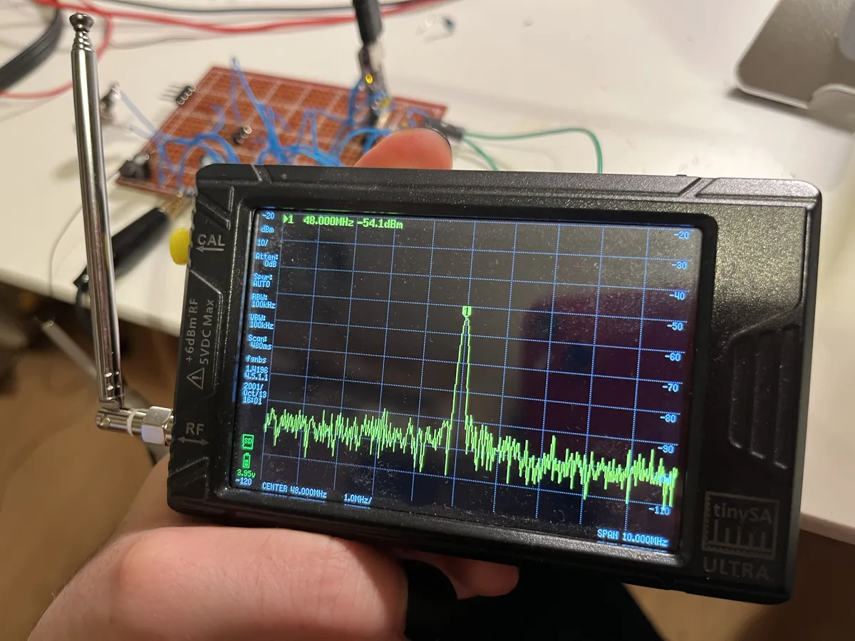 Carrier signal radiating from the mess-of-wires prototype
I experimented with a couple of basic mixer circuits (like the single diode design shown below) and all of them produced a working result on my receiver. However, they were quite finicky on the protoboard and I wasn't sure how well the results would transfer to the final PCB.
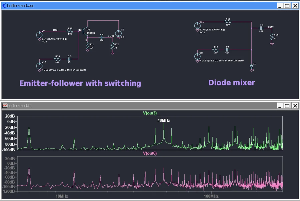 Some basic mixers I tried
Since we gained some extra space by switching to a larger plug, I ended up with this slightly more complicated, but still hacky two-transistor design with added filtering. The main advantage of this design is slightly improved linearity, which should translate to better color reproduction (see Differential Gain and Phase).
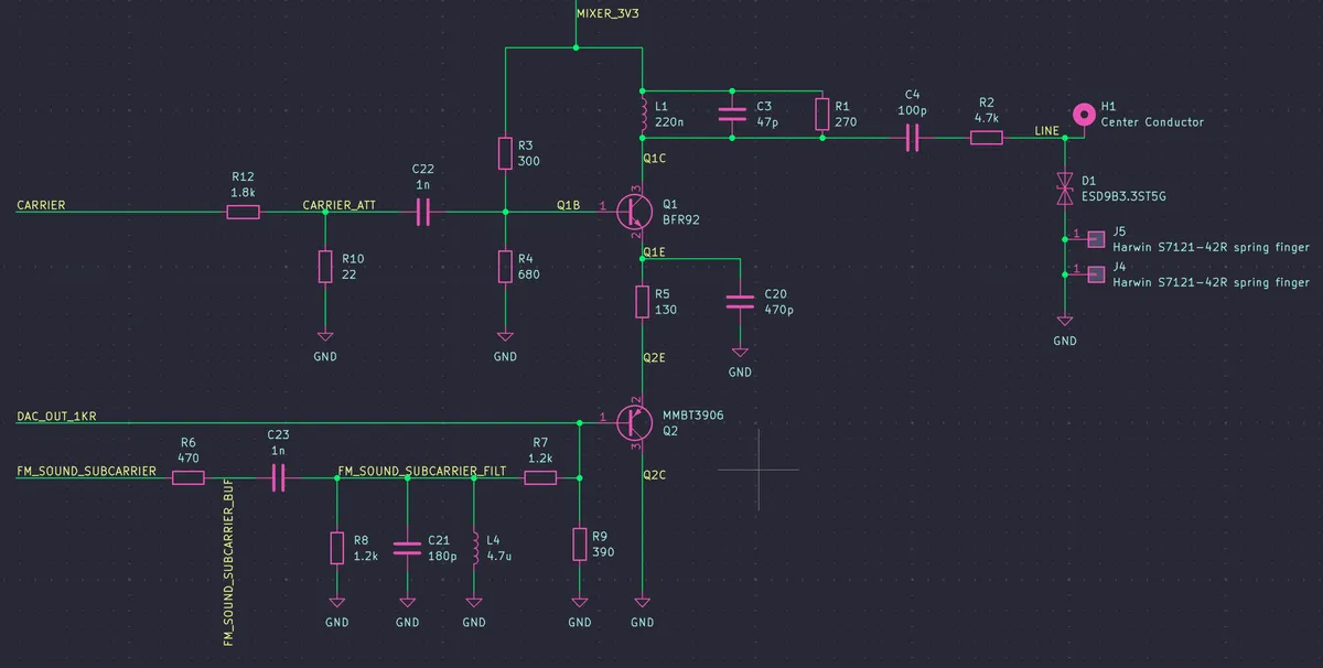
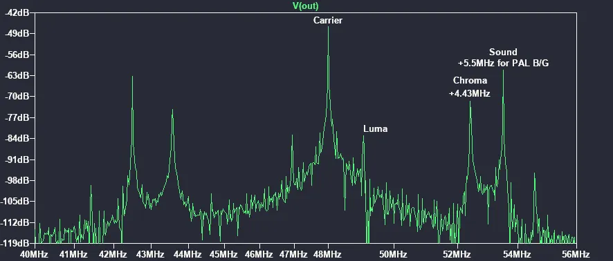 Simulated spectrum of the two transistor mixer
As for the mixer circuit, it ended up producing better colour and more stable image than the simpler experiments. However, it trades that accuracy for modulation depth, which results in rather poor contrast/dark image (in PAL-B the modulation is negative, meaning a lower carrier amplitude produces brighter image). One could imagine fitting a more complex circuit.
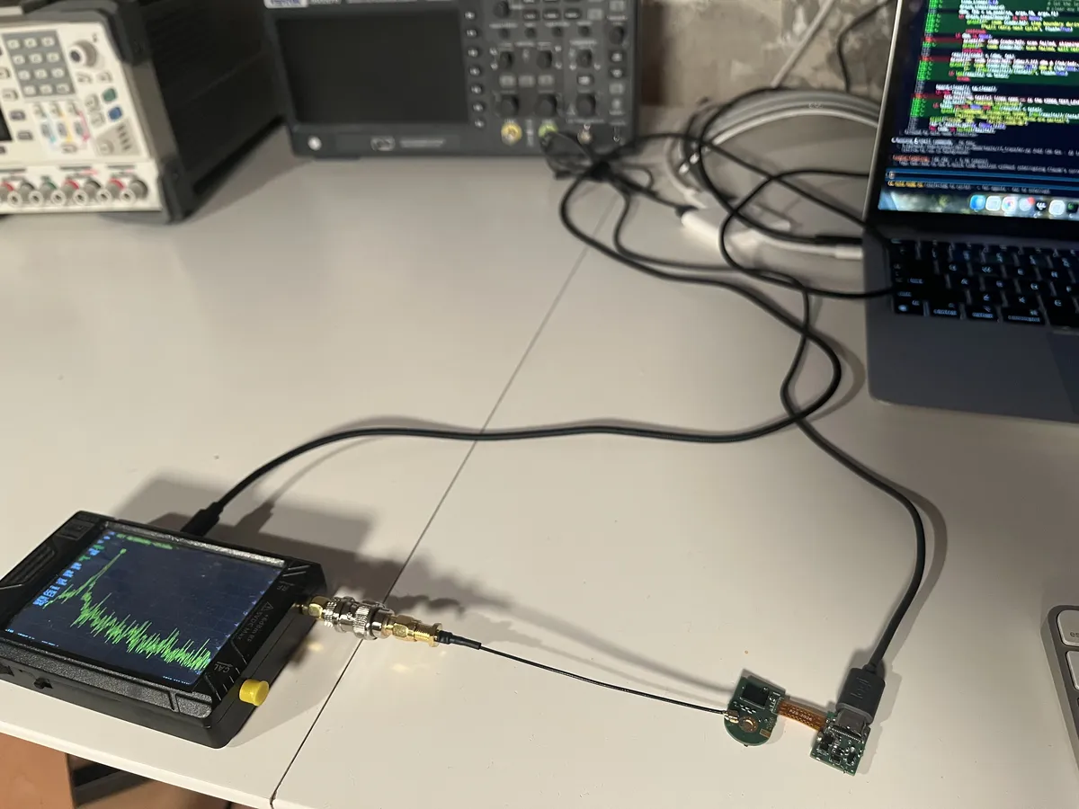
In the end I went with an 8-bit R-2R DAC instead of the distinct resistor values. It was easier to easier to find precision components for generic values + there was still plenty of space on the final PCB. Even if the color space of the game does not utilise the full resolution, the extra bits come in handy when calibrating out the non-linearity of the mixer, which was done by measuring the output on an SDR and the TinySA and adjusting a lookup table accordingly.
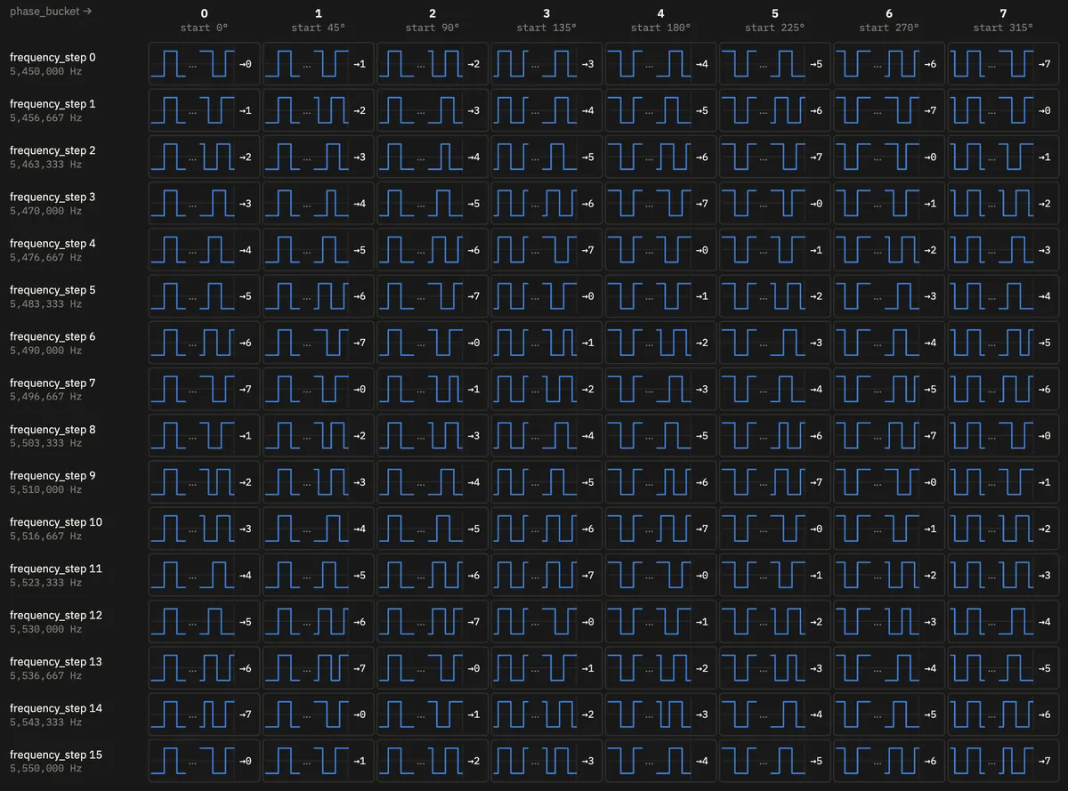 Bit pattern LUT used to generate the FM sound signal
Ironically, the sound carrier is produced using I²S but instead of outputting PCM, we abuse it to bang out a bit pattern with the right (average) switching frequency. We apply a similar waveform pre-baking trick we used for the video signal — a table contains prepared bit sequences for a given frequency and phase offset. To maintain coherence, we track phase sequence-to-sequence.
Audio produced this way ended up quite noisy and despite my attempt to bandpass filter the square wave, leaks into the video quit.
Bluetooth gamepad input
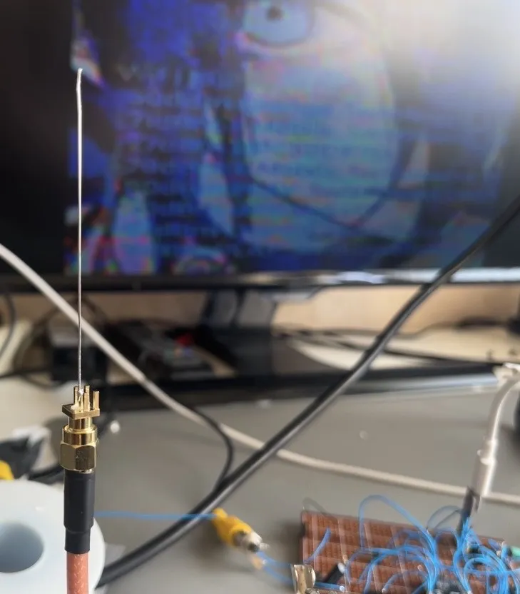 Improvised tuned antenna
The ESP32-S3 comes with built-in Bluetooth Low Energy (no regular Bluetooth) interface. Conveniently, the recent Xbox controllers also talk over BLE.
I'm definitely no RF expert, but I wanted some sort of antenna that would fit in the design and allow the rest of the plug to be fully shielded. I expected the system to be radiating like crazy given our makeshift LO and mixer, and I rather not get a visit from authorities for interfering with a grandma's radio with my Doom sound broadcast (second harmonic of our modulated signal lands just right in the FM radio band). Shielding, in conjunction with limited board area, makes relying on trace or chip antennas rather difficult. I experimented with a piece of solid-core wire, length tuned to both a half and a quarter of 2.4GHz wave's length, soldered to an SMA connector. It actually performed quite a bit better than a tiny commercial U.FL-connected PCB antenna. Even an open SMA connector was enough for the gamepad and WiFi to work. The final build has the wire sticking away from the PCB, forming a sort of a dipole with the plug's body. Performance must be good enough just for a couple of meters of range anyway — though decent WiFi connectivity also comes useful as I can have a bootloader download game images over the air.
Making a sandwich
To maximize the use of available volume, I went for two PCBs connected together with an FPC — one of the ways of making systems really small. A single-piece "rigid-flex" board could be even better for this application, but that technology is quite expensive. I was convinced a similar result could be achieved by soldering the distinct pieces together.
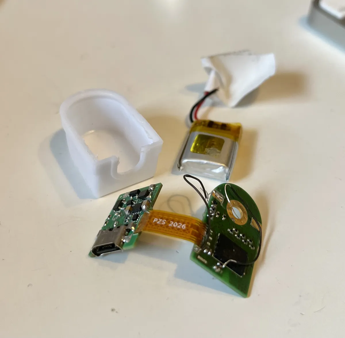
It was my first time designing a flex board and assembly ended up being the most annoying part of the project. Multiple traces were torn trying to make the connection work. In hindsight, I shouldn't have made the copper area unbalanced by making the power supply traces much thicker. That made soldering the interconnect a nightmare. I definitely could have paid more attention to the mechanical aspect and made life easier for myself. I think making the traces equal-width and adding some vias to transfer heat when hand-soldering board to board would have gone a long way.
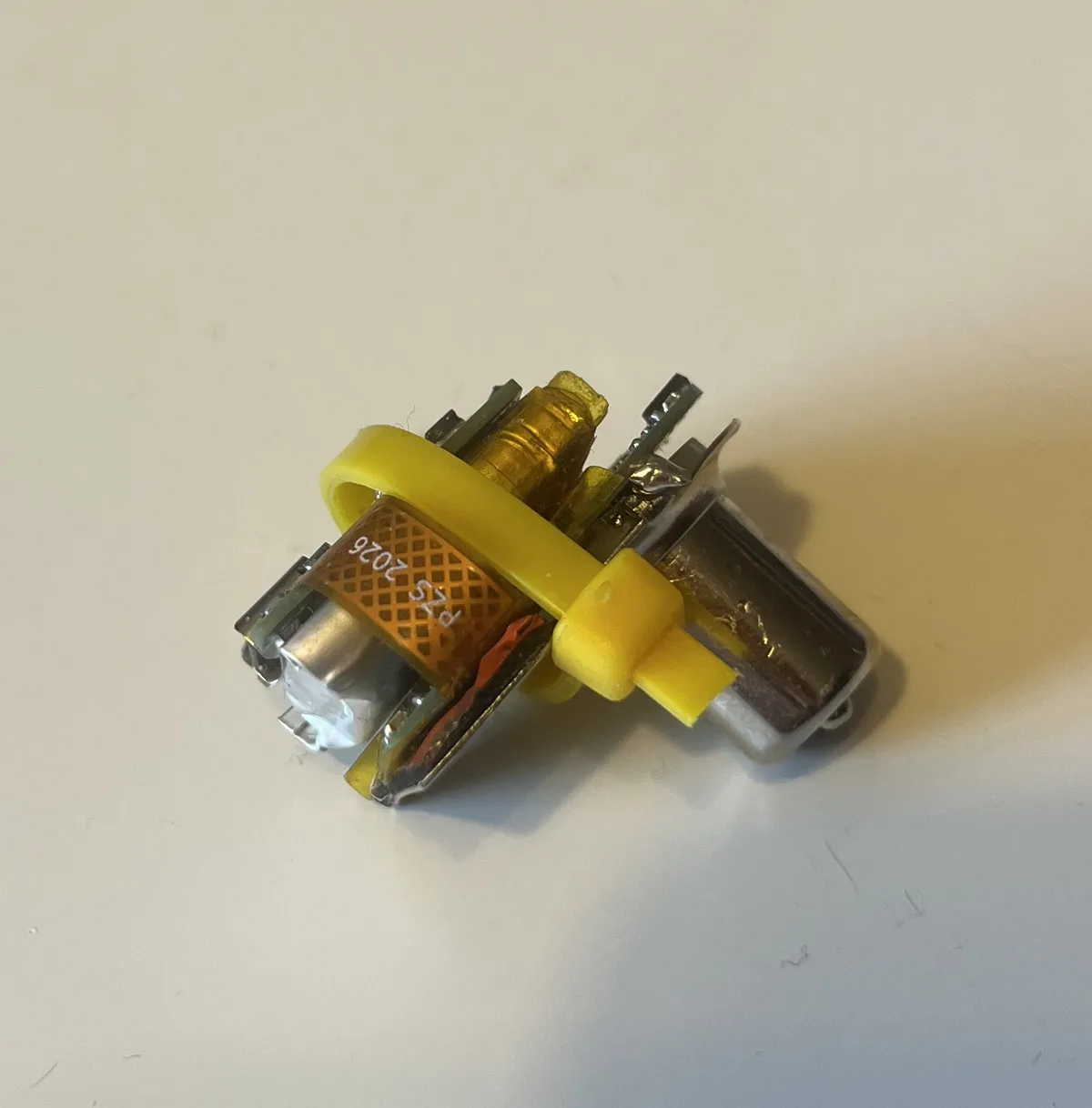 How the thing goes together inside the plug
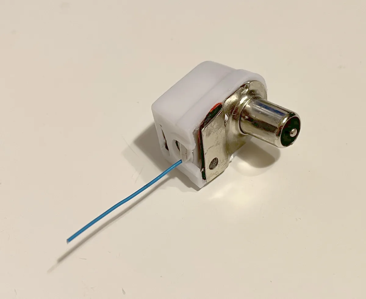 The plug after assembly
Project files
Everything can be found on github.
You can explore the hardware files in KiCanvas.